QUAD OF APPLIED ARTS
w/ Ashley Su, Jackie Yu, and Norman Situ
The Quad of Applied Arts is a proposal centered around bridging the gap in the School of Architecture(SoA). Due to the current state of CMU SoA being dispersed across two buildings, Margaret Morrison Carnegie Hall and College of Fine Arts, there is a lack of identity for SoA in the broader campus. Our proposal focuses on bridging these two buildings by filling up the currently occupied parking lot with an underground addition, and repurposeing the exisitng parking lot into a Quad. As students who have experienced CMU SOA, we’ve found that architecture is one of the few disciplines in which students live and work within our subject of study. Because of this, we found it important to create a space that reflects the use and needs of the students and faculty while emphasizing its presence on campus.
The Department of Architecture began as a part of the College of Fine Arts, formerly known as the School of Applied Design. Although SOA is housed in the CFA and MM, these two buildings also house the School of Music, Art and Design. The Quad of Applied Arts is not only creating outdoor space for the SOA but also the other schools within the college of fine arts. This open space draws from the legacy of space-making in the larger campus and mirrors the intentions of the campus planning
Due to the separation of SOA into two different buildings, some problems that SOA is challenged with are the absence of a campus presence. Our proposal sits in the existing parking lot between MM and CFA to take advantage of the view from The Cut down towards Margaret Morrison St. This site selection helps to activate the middle ground between the two buildings, creating not only a visual connection but also marks the new presence of the School of Architecture.

PROPOSED ADDITION
Our proposal contains 3 main components that mark the presence of the School of Architecture, the above grade building mass, the Quad, and the Subgrade level.
We have chosen to occupy what is currently the CFA parking lot. Not only is it a poorly utilized space, it has so much potential as it is bordered by CFA, Posner Hall, Posner Center and MM. Our project creates an above-ground visual experience as well as underground connection between MM and CFA. Buildings being connected is a common occurrence on campus and it drastically improves student commute experience during harsh Pittsburgh weathers. We maintain a small building footprint above ground as we acknowledge a part of campus that is already crowded with buildings. Instead, the quad reactivates pathways and adjacencies across the number garden, and brings an identity to not just the School of Architecture, but also the College of Fine Arts as a whole.

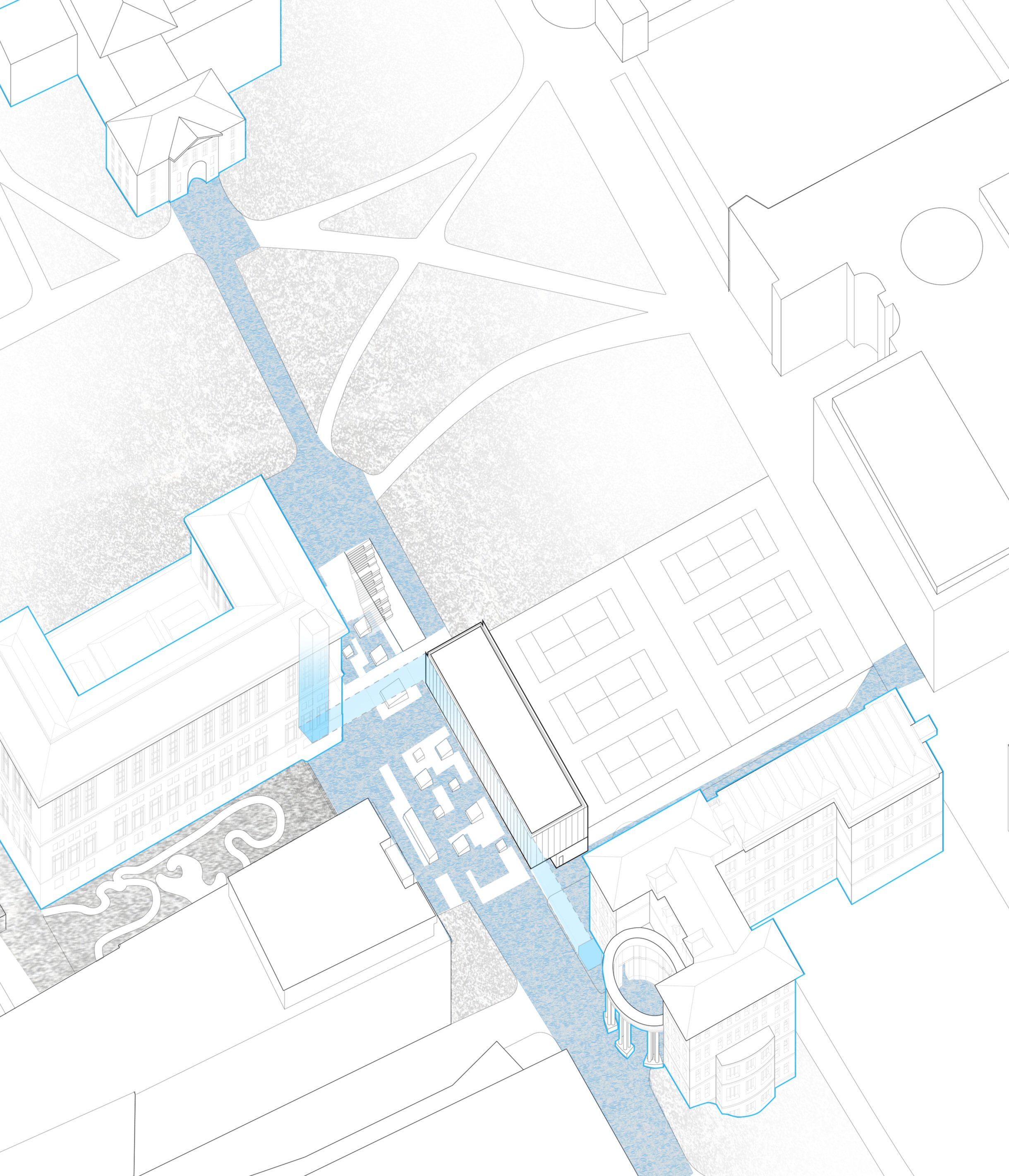
Site plan


Short Section Perspective
ABOVE GRADE ADDITION
On the quad level, the building holds a gallery space that houses temporary exhibitions for student/faculty work and can conform to more open layouts for workshops shared between CFA schools. Both northern and southern facades are glass to encourage people to come inside while passing by the building. We envision a blend of landscaping and skylights for people to peer into the workings of SOA students below to create a quad. Open to the public, this level incents a place for meandering and lingering that allows the School of Architecture to further mark its presence and connect with other colleges. A mix of multipurpose space and seating framed by lawn and perennials slows down the pace within the quad and allows for unprogrammed flexible areas students across schools can use.
Moving into the building, the second floor is cantilever above the quad and over the exhibition space. The space between the cantilever and CFA frames a view to MM on the east side, as well as Doherty Hall on the west. In addition, the cantilever also provides a programmatic solution for the need for additional studio spaces. The space is laid out in a traditional foundation studio fashion with critique nooks along the north side overlooking the tennis courts.

Above grade floor plans
SUBGRADE ADDITION
Descending below the Quad through the sinking stairways is the new front entrance for the School of Architecture. The subgrade level opens out to the tennis courts and spans the full parking lot from the edge of MM to the front edge of CFA.
Greeted by the main lobby, the 2 main circulation axes provide the organization for 32,000 sq ft space. The 2 axes are reinforced with 20’ corridors which act as a bridge for the rest of the school as well as for SOA.
Surrounding these wide corridors are faculty offices, advanced studios, a lecture hall, DFAB space, an archival library (spirit of original archival lib. of CFA), meeting rooms, a cafe, and lounge. These programmatic spaces are decorated with sliding partitions and glazing that promote the interaction of programs across the building’s floor plan including the corridors.
Moving into the studio space underground, it is governed by an open-floor plan concept prompting cross-studio collaboration. Dedicated crit and review spaces are scattered throughout the studio which are framed by adjustable walls and occur under large skylights. Similar to the crit spaces, skylights frame programmatic spaces such as the main lobby, the library, and Dfab.

Subgrade floor plan

Perspective: Underground studio

Perspective: lobby looking towards digital fabrication lab
STEEL STRUCTURE
The proposed building is a type 2B building with its structure comprised of non combustible materials such as steel framing and concrete retaining walls. The building’s structure has distinct characteristics each level to suit different structural needs: Our main addition underground and the quad above is supported by a double-layered waffle grid system. The waffle grid is made up of prefabricated 4’ individual C 8 channel units that are pieced together into 8’ x 40’ panels with each unit bolted into ½” cruciform steel plate as connections. The assembled 40’ waffle modules are then hoisted up and supported by 10” HSS columns; the columns and waffle modules are connected through the cruciform which extend down and form a notch which is then secured with a welded connection. These HSS columns span 40’ apart for the underground area, but condenses into 20’ in the areas where it also supports upper levels. As we move to the upper levels we have a dominant 40” deep I beam (w 40 x 431) carries the load of the cantilever. Finally, the steel framing above is w 18 (x 40) as primary and w 12 ( x 26) tertiary with its primary purpose to support the roof.

Joinery details

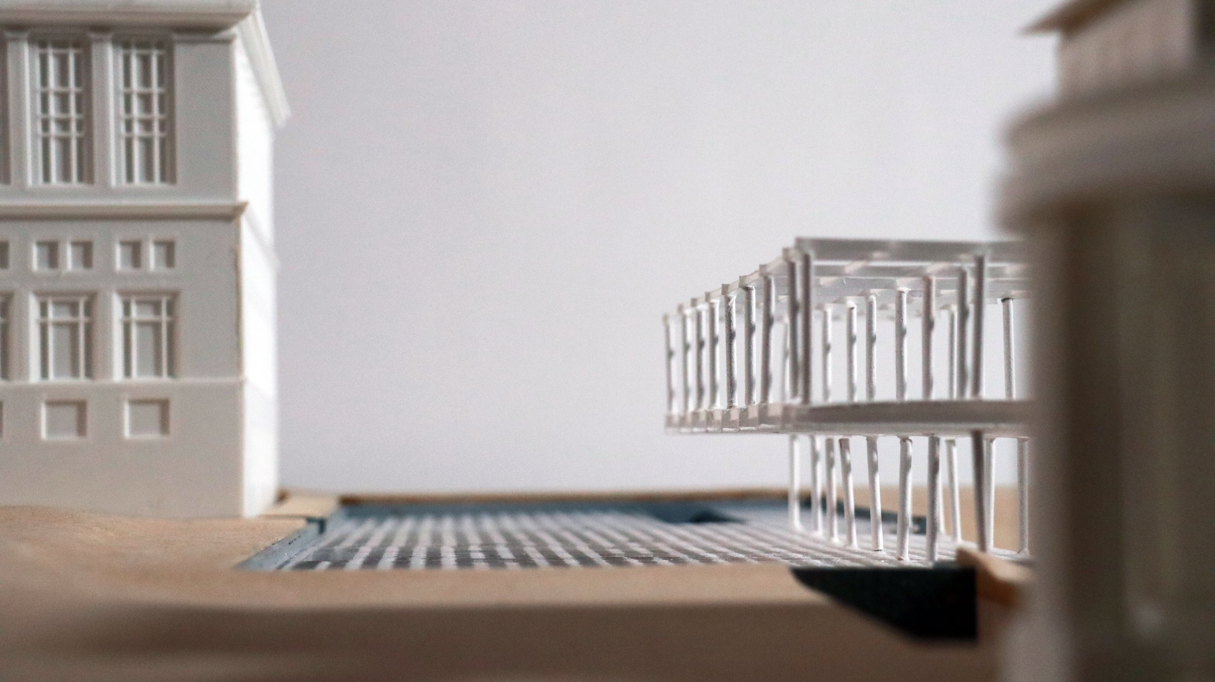
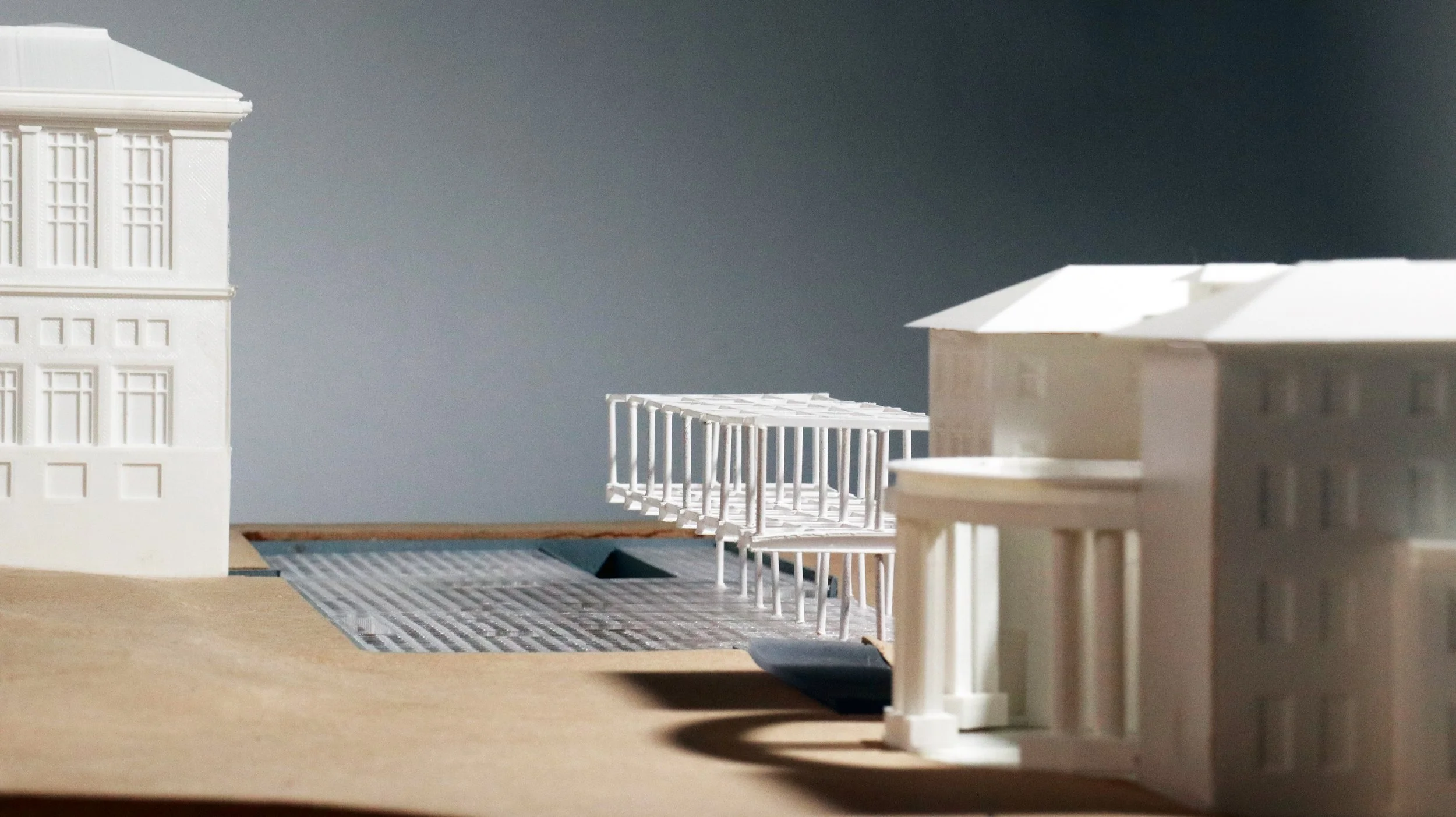
Structural composition

Modular assembly sequence


HVAC exploded axon
INTEGRATING MECHANICAL HEATING, COOLING, AND VENTILATION
Our addition is dependent on the centralized system from campus including water and steam from the tunnels to run our heating and cooling. The mechanical system that our group has selected for our design is a Variable Air Volume system (VAV). It is a central ventilation system including heating and cooling. A Central Air Handling Unit Supply Fan (AHU) is located in the equipment room on the lower level, providing heating and cooling, and ventilation to all three levels.
We chose the VAV system because of its omission of Rooftop Units. Because our roof is visible from both CFA and MM, we chose not to install RTUs to eliminate visual obstructions on the rooftop. Furthermore, we take advantage of the campus chilled water line which also eliminates the need for a standalone chiller. Due to the majority of our footprint being underground, the lack of direct solar radiation and infiltration loads leads to a minimal cooling and heating load. This allows us to only have one AHU unit to provide enough heating, cooling, and ventilation into the building. In addition, the minimal need for these loads allows us to tap into the campus chilled water line without jeopardizing its limited capacity.
Due to programmatic space needs, we are utilizing VAV systems to establish zones for a more economical and energy-efficient approach. In total, there are 13 zones across all 3 levels. These zones are categorized by spaces that are required to house larger occupancy capacities, require individual thermal control, are limited by location, or house lab equipment. These zones are accessorized with their own thermostats for occupant flexibility and occupancy sensors to reduce equipment energy loads when these spaces are not occupied. This approach is applied as these spaces have different schedules such as DFAB spaces that are open more during the day versus studio spaces that are accessible 24/7.
The conditioned air is distributed throughout the building through the main arteries that weave around the skylights in between the structural grid, through the circulation space, and up the shaft to the two floors above.

HVAC plans

HVAC zones

Skylight section detail

Drainage Detail
SKYLIGHTS
To support meandering throughout the quad, the ground plane is thought of as an occupiable roof and employs the American hydro tech-intensive green roof system to support our landscaping and the foot traffic above. This consists of a 2’ waters encompassing of garden media, system filer, root barrier, dow styrofoam insulation, and roofing membrane that sits on top of the concrete ceiling slab. The skylight continues the c-channel modular grid structure with bent steel plates at the corner connections. Sandwiched by 2 bent steel plates at each corner, the C-channel runs vertically to frame the skylights.

Skylight axon diagram

Drainage Plan

Perspective: underground archive looking towards studio space
ENVELOPE
With glazing along both north and south facades, our new addition becomes a beacon of light that brings a new sense of identity to the school of architecture. Maintaining visual connection into the tennis courts and toward our quad lead to the selection of a perforated metal mesh screen that encases the building above ground.
Our Window to Wall Ratio is 23% which complies with the ASHRAE 90.1 code minimum of 30%. This means we have already reduced the heat loss through the wall fenestration. However, since most of our glazing is placed on the North and South facades of our Ground and Upper levels, we implemented a perforated metal scrim in an effort to neutralize our envelope even further. This screen allows us to reduce solar radiation and heat gain through the windows while maintaining visual transparency on the North and Southern facades.

Elevation diagram: referencing context

North Facing Elevation

South Facing Elevation

Perspective: south façade from quad

Curtain wall section detail

cantilever section detail
METHOD OF MEASURE
Looking at the Climate Studio simulations, the lower level exhibition receives comfortable daylight and minimal glare due to the cantilever on the south side. This allows us to omit any additional envelope elements on that facade. However, on the upper level studio floor, the glazing on the southern facade results in uncomfortable glare. Maximizing daylighting from the north for diffused light, the north side scrim begins to include cutouts that align with surrounding context. The imagery of the new SOA logo is projected on the north facade and reflects the change in sizes of perforations. Meanwhile, on the south, the perforations are uniform to reduce the glare and the design remains simple to emphasize the strong linear proportion of the building.
Energy pathways analysis suggests including batt insulation inside metal stud cavity results in condensation occurring inside exterior envelop. 6.5 inch of mineral wool insulation is installed to meet R value requirements and prevent unwanted condensation within envelope.
The electrical lighting for the building is designed through studying the optimal lux levels for each of the main spaces. For the lower level, we sized and arranged lighting fixtures in relation to the structural grid and around skylights to create a coherent visual experience. Primarily use dimmable LED lights with occupancy sensing which will also reflect the programmatic use of spaces with colder lights in studios and Dfab and warmer lights in the archive and lounges.

climate studio analysis

lighting plans

therm energy pathway analysis

lighting simulation
